Control Unit Implementation
In this project, the control algorithms are executed in Simulink, with the data acquisition device interfacing with MATLAB through a serial COM port. Real-time communication is facilitated by the Real-Time Desktop package for MATLAB. To test new control algorithms, simply replace the controller block in the provided template.
The complete project repository is available on GitHub: Roman3D Project Repo
Real-Time Desktop Kernel Setup
Install the Real-Time Desktop Kernel on the host computer by executing the following command in the MATLAB command window:
1
 sldrtkernel -install
To verify the installation, use the command:
1
rtwho
Example output:
Simulink configuration
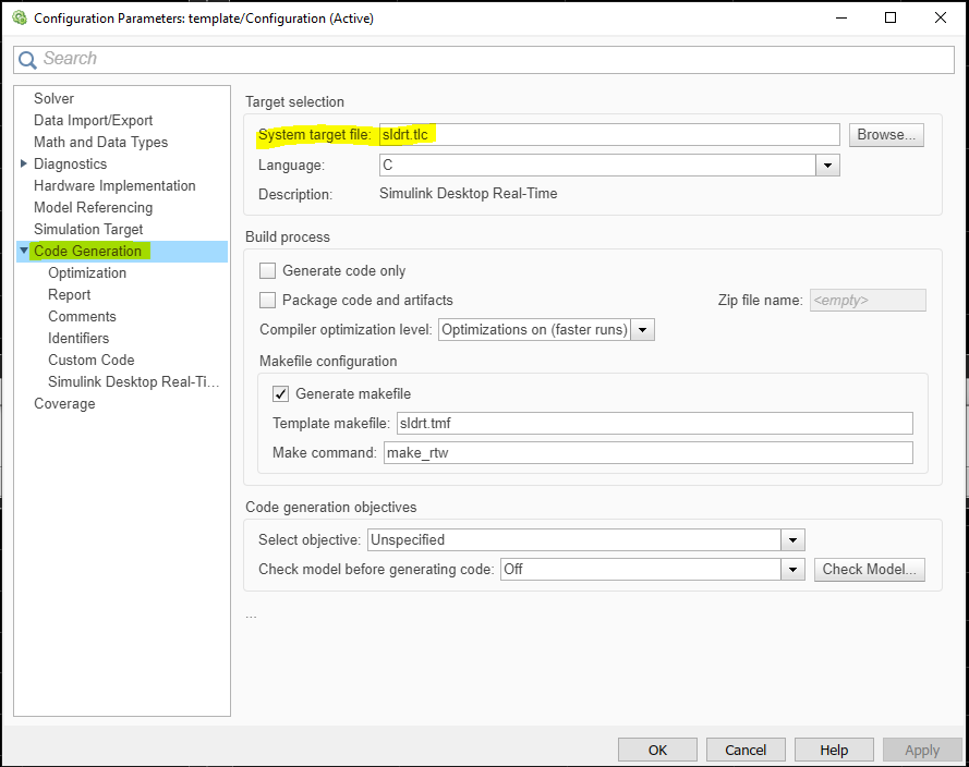
After creating a Simulink project, configure it for the real-time kernel by following these steps:
- Go to Model settings.
- Navigate to Code Generation.
- Set the System target file to
sldrt.tlc.
After this configuration, a new tab named Desktop Real-Time will appear in Simulink. Start simulations from this tab using the Run In Real Time button:
Encoder Input Configuration
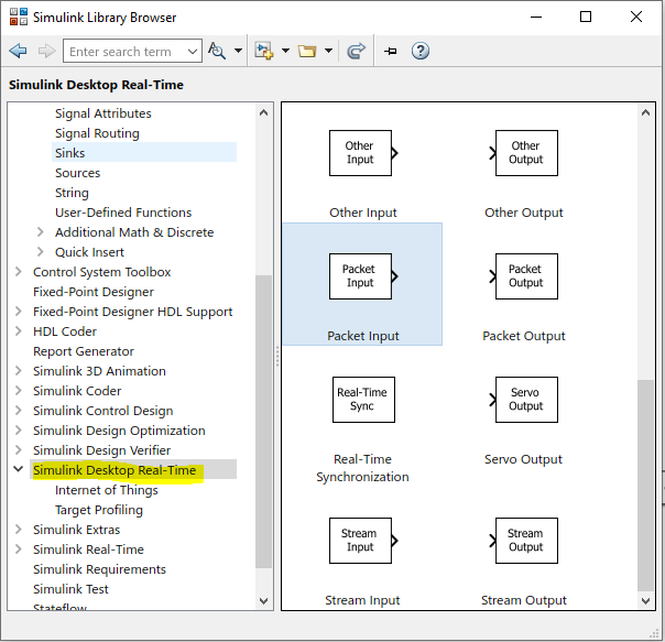
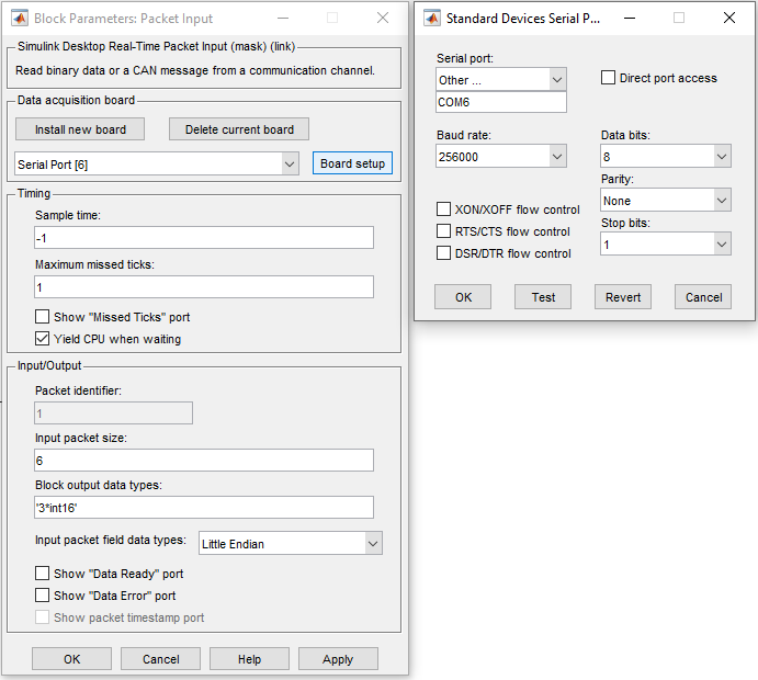
To communicate with the device, add a Packet Input block from the Simulink Desktop Real-Time Library:
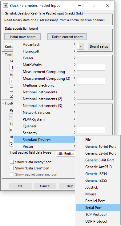
Install a new serial port board as shown:
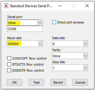
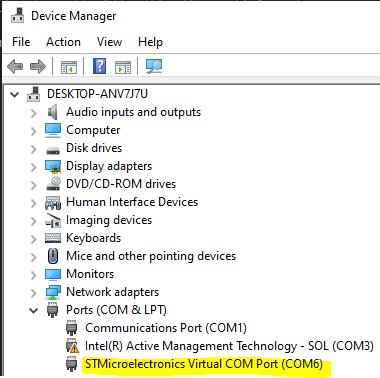
Select the serial port according to the device manager:
Configure the device to send encoder input in 16-bit integer format at Block output data types:
Now, convert the encoder input to radians. First, convert int16 to double using a convert block:
DAC Output Configurations
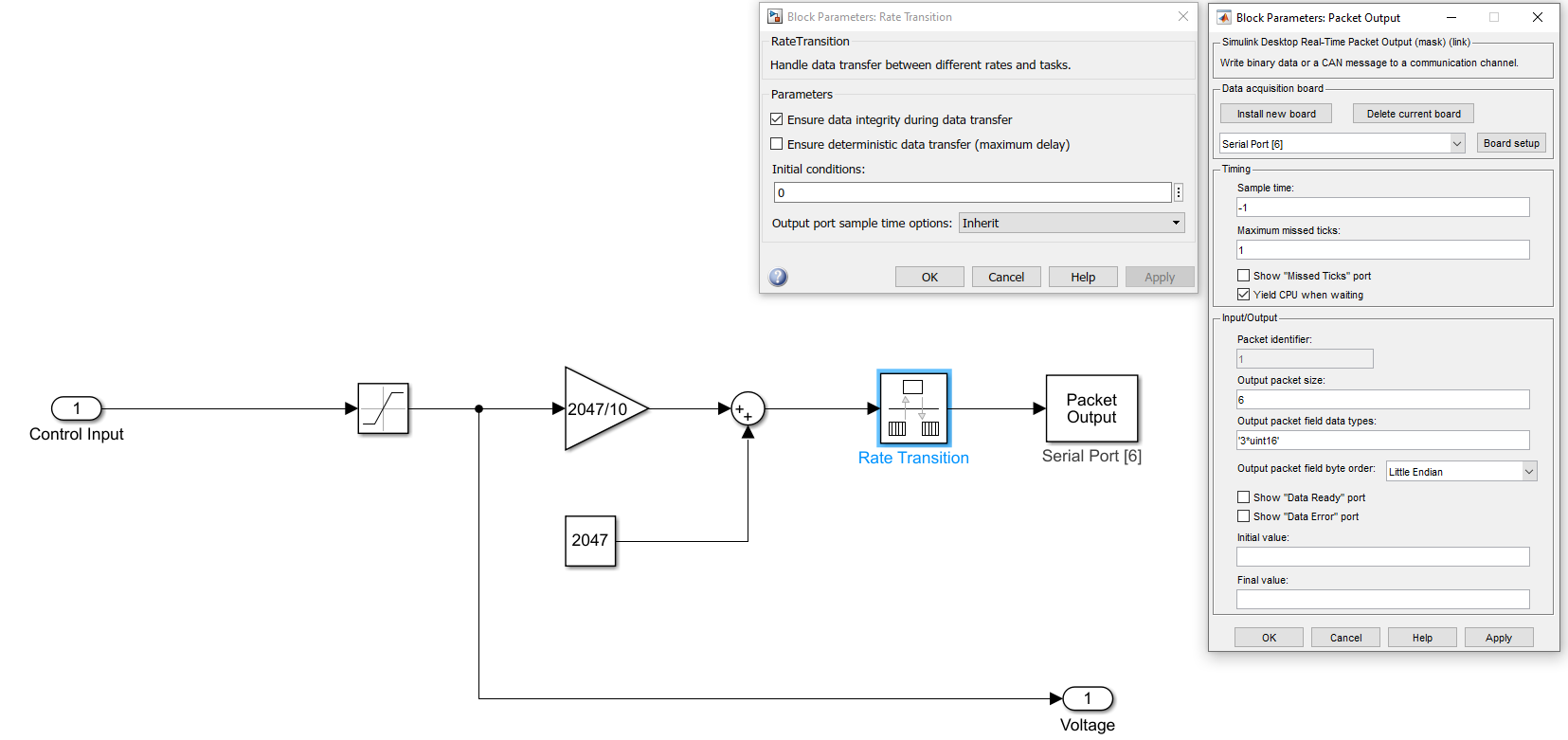
To send DAC values to the device, use the Packet Output block from the Simulink Desktop Real-Time library. Calculate the real DAC value by converting +/- 10V to a 0-4096 range in MATLAB. Also, include a Rate Transition block before outputting DAC values:
